Rendering a Triangle to the Screen
In this chapter, we'll finally be getting to render something to the screen! Exciting stuff. We're going to start with something simple: a triangle!
The Graphics Rendering Pipeline
Before we can render our triangle, it has to pass through something called the "Graphics Pipeline". The Graphics Pipeline is the series of steps that we must go through to render objects to our screen:
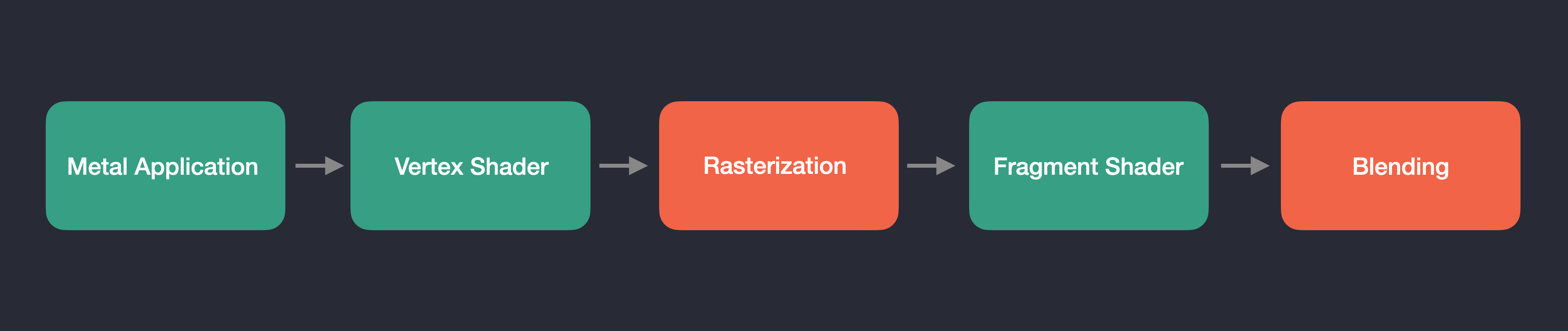
The steps listed in green are fully programmable by you. We write the code for the C++ application as well as the Vertex and Fragment Shader programs that are executed on the GPU. GPUs are massively parallel devices, and Shader programs are specifically designed to take advantage of this fact. Unlike with CPUs where you might have 4, 8, 16, or maybe even 32 individual cores, GPUs have hundrends and thousands of them, all running in parallel. Vertex shaders are designed to operate on the vertices of the meshes in our scene concurrently. Initially, our Vertex Shader will transform all 3 vertices of our triangle mesh at once, and this process will scale continously as we render more complicated scenes with more complicated meshes. A similar logic applies with the Fragment Shader. The Fragment Shader (sometimes called the "Pixel" Shader) operates on each pixel that we'll want to render, as determined by the output of the Rasterization stage. Modern displays have many individual pixels on them, which makes them a perfect candidate for GPU processing. The steps highlighted above in red are not programmable stages, but are instead configurable. We'll modify them as necessary in the following lessons. Here is a more detailed description of the steps involved in the Graphics Pipeline:
- The Application Stage: In our case, the "Application Stage" involves setting up our
MTLEngine, intializing the Metal device, configuring a GLFW window, compiling shader code into a library, creating command buffers, encoding draw commands, managing the render loop, and more. This stage represents the C++ side of the process, preparing the environment for encoding GPU commands for rendering or compute related tasks. - The Vertex Shader Stage: This is the stage in the pipeline where the GPU comes into play. In other Graphics APIs such as DirectX, typically the second stage of the Graphics Pipeline starts with something called the "Input Assembler", which is responsible for collecting and organizing vertex data from memory buffers on the GPU and feeding them into the rendering pipeline. In Metal, this functionality is integrated with the Vertex Shader stage. The Vertex Shader is responsible for processing vertex data, applying transformations, and passing the resulting data to the next stages of the rendering pipeline. To feed vertex data into the Vertex Shader in Metal, you define vertex descriptors that specify the layout and format of the vertex data. These descriptors are used to map vertex data from the vertex buffers to the input attributes of the Vertex Shader. This process effectively replaces the Input Assembler stage found in other Graphics APIs, streamlining the rendering pipeline in Metal.
- The Rasterization Stage: In Metal, the Rasterization Stage converts vector-based geometry (aka vertices) into pixel-based fragments. It processes transformed vertices from the Vertex Shader, assembles them into primitives, interpolates attributes, performs perspective division, clips vertices to the view frustum, and identifies the pixels we want to shade within the rendered geometry. This stage effectively prepares the pixels or "fragments" for further processing and shading in the Fragment Shader Stage.
- The Fragment Shader Stage: The Fragment Shader in Metal is responsible for processing and shading pixel-based fragments generated during rasterization. The Fragment Shader is executed for each pixel on the screen, and typically performs a series of mathematical operations to calculate the final color of the pixel, such as texture sampling, lighting and material property calculations, blending with the color of nearby pixels, etc. Once processed, the fragments are combined to create the final rendered image on the screen.
- The Blending Stage: The Blending stage in Metal is responsible for combining the output of the Fragment Shader stage with the existing data in the framebuffer, considering factors like transparency, translucency, and depth. It determines how the final color of each pixel is calculated by blending the incoming fragment color with the color already present in the framebuffer, ultimately producing the final rendered image on the screen.
Additionally, we also have another type of shader called "Compute Shaders". A Compute Shader is a program that runs on the GPU, seperate from the traditional rendering pipeline. It is used to perform general-purpose computational tasks that are generally (but not always) unrelated to rendering, such as image and audio processing, phsysics simulation, and machine learning. Compute shaders provide for an incredibly high degree of parallelism, and allow a user to perform parallel operations and algorithms much faster than on the CPU. We'll get into more detail about how we can use these in the Advanced Chapters later on.
Now that I've described the Graphics Pipeline and these things called Shaders, let's get to writing some.
To render our triangle, we'll need to create a new shader file in our Xcode project called triangle.metal. Unlike other Graphics APIs, in Metal there is only one file extension for writing shaders. You use the function definition to define a function as a vertex, fragment, or compute function. In our new Shader file, we're going to write two shader functions, correspondingly titled vertexShader() and fragmentShader():
using namespace metal;. We need to pre-pend our vertexShader() function definition with the vertex keyword to tell Metal that this is a vertex function. We'll be returning a float4, made up of the position of each vertex in the triangle. Shader programs run concurrently on the GPU, so each vertex we input will be processed simultaneously. To render our triangle, since we have three input vertices, we'll really have three instances of this vertexShader() function running at the same time. This is why the first take in the vertexID as input, so that we can know which vertex we're working on. The second input is our triangle's vertexPositions buffer. You'll notice the constant keyword prepended to our type definition. This is called an address space attribute, and it dictates the region of memory that the buffer is located in on the GPU. Quoting the Metal Specification directly, "the constant address space name refers to buffer memory objects allocated from the device memory pool that are read-only". Essentially, the buffer is allocated on the GPU in read-only memory, we aren't going to be able to change it. You can read more about address spaces in section 4.0 of the Metal Specification. We'll use our vertexID to index the proper Vertex per Shader, and we're going to cast our vertexPositions to a larger homogeneous vector type of float4, as Vertex functions are required to output positions in four-dimensional clip-space coordinates. Here's a great write-up on why that's necessary over at learnopengl.com.
Similarly, our fragmentShader() will output a float4 of color values at each triangle Vertex, and interpolate between them. Since we're just returning the same color at each Vertex, the whole triangle will be the same color, as there aren't any other colors to interpolate between. You can fill these with any value's between 0.0-1.0, Red, Green, Blue. The input vertexPositions to the fragmentShader() isn't necessary quite yet, but it's there as a demonstration on how you would pass the vertexPositions for use within the Fragment shader. We'll make use of it once we have a triangle rendering.
#include <simd/simd.h>

class MTLEngine {
public:
    void init();
    void run();
    void cleanup();

private:
    void initDevice();
    void initWindow();

    void createTriangle();
    void createDefaultLibrary();
    void createCommandQueue();
    void createRenderPipeline();

    void encodeRenderCommand(MTL::RenderCommandEncoder* renderEncoder);
    void sendRenderCommand();
    void draw();

    MTL::Device* metalDevice;
    GLFWwindow* glfwWindow;
    NSWindow* metalWindow;
    CAMetalLayer* metalLayer;
    CA::MetalDrawable* metalDrawable;

    MTL::Library* metalDefaultLibrary;
    MTL::CommandQueue* metalCommandQueue;
    MTL::CommandBuffer* metalCommandBuffer;
    MTL::RenderPipelineState* metalRenderPSO;
    MTL::Buffer* triangleVertexBuffer;
};
The first addition is createTriangle():
| mtl_engine.mm | |
|---|---|
init() function after we initialize our Metal device and GLFW window. Given that our goal is to render a triangle, we first define some triangle vertices with our simd::float3 vector type included from Apple's <simd/simd.h> library. The simd library is kind of Apple's equivalent to the glm library if you've worked with Vulkan or OpenGL. In fact, you can use glm, however there are some important differences to take into account. We'll use the simd library throughout this tutorial series to make it easier on ourselves.
We then ask our Metal device to create a new Metal Buffer, copying our triangle vertices over to the GPU. You can think of a MTL::Buffer object like a buffer of data in any programming language, it's simply used to store data. Metal doesn't know anything about the contents or layout of the data - you can customize it however you like. All it knows is the size of the buffer, as it's the second argument you pass in to newBuffer(). You might notice the third argument, MTL::ResourceStorageModeShared. This tells Metal to give both the CPU and GPU the ability to access the object. We'll discuss the other two types of storage modes later on.
The next addition to our MTLEngine is createDefaultLibrary():
| mtl_engine.mm | |
|---|---|
init() function after we create our triangle and copy it to the GPU. The first thing we're going to do is access our metalDevice to create a new default library. Xcode automatically compiles all Metal source files (ending in .metal) within an Xcode project into a single default library upon project compilation. In our case, because we're not compiling our Metal source code at runtime, our MTL::Library* object will give us access to all of our Metal source code from a single source, making it very simple to access and manage. If for any reason we're unable to load our compiled Metal binaries, we'll exit. If for any reason later on you get any errors here, make sure that your Metal source files are added as compile targets in the Build Phases section of the project.
| mtl_engine.mm | |
|---|---|
The "Metal Flow"
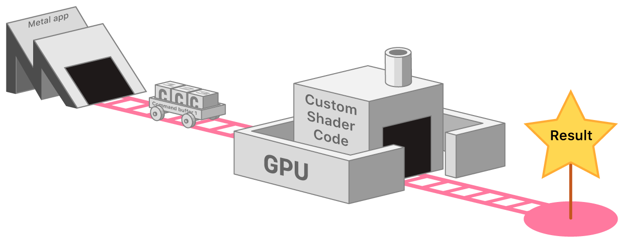 This image describes what I call the "Metal Flow"1. The "Metal Flow" can be summarized as follows: To perform graphics tasks in Metal, we first create a "Command Queue", which acts as the railway tracks in the above image. Multiple railway cars, or "Command Buffers", can run on these tracks concurrently. Command Buffers store individual "Commands" that instruct the GPU, such as drawing a triangle. These commands are executed on the GPU using "Shader Code" within programs called Shaders, like we discussed previously.
Command Queues and Command Buffers
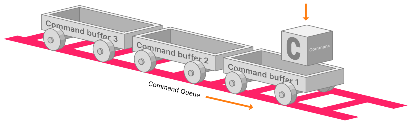
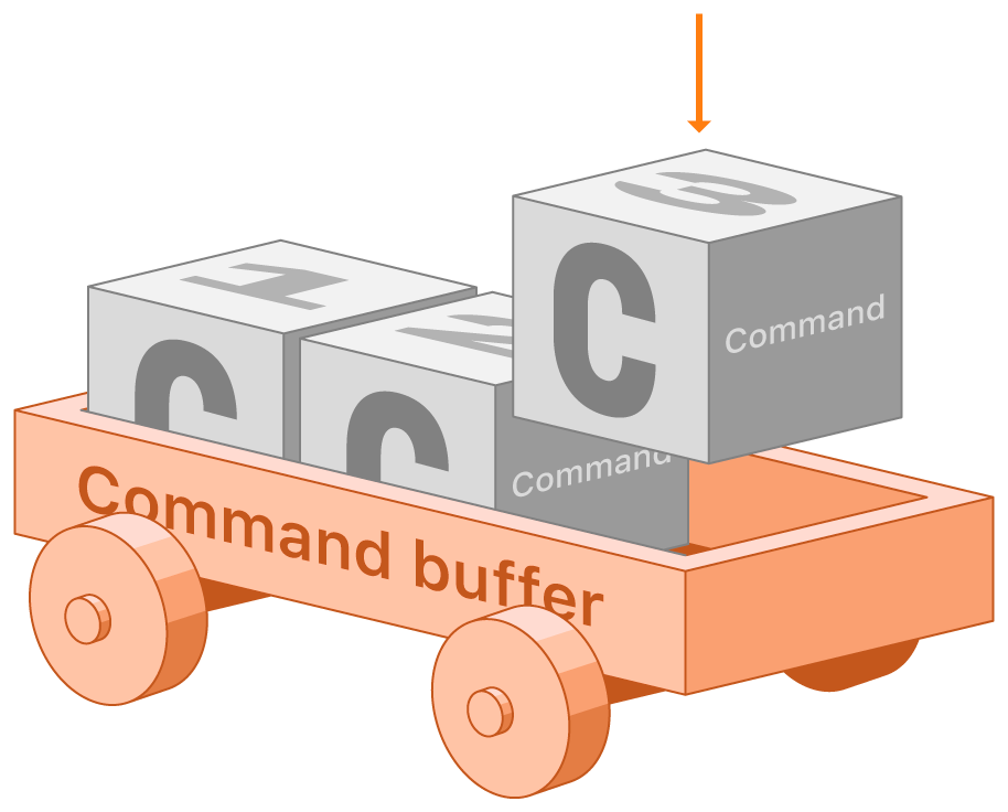
A Command Queue allows us to create Command Buffers, which essentially represent a chunk of work for the GPU. We use Command Buffers by encoding individual commands into them via something called a Command Encoder, like for setting and rendering our triangle vertex data, or telling the GPU to draw our primitives.
| Command Queue |
|---|
 |
| Command Encoder | Command Buffer |
|---|---|
 |
 |
A Command Queue is responsible for creating Command Buffers, which represent a set of tasks for the GPU. Command Encoders are used to encode individual commands into these buffers, such as rendering and drawing operations. You can create multiple Command Buffers within a Command Queue, which can offer various benefits, including concurrent execution, improved resource usage, increased flexibility, and efficient render pass management. In essence, a single Command Queue allows the creation of Command Buffers to organize GPU tasks, with Command Encoders facilitating the encoding of commands into these buffers.
Render Pipelines
We're now going to create our Render Pipeline.
A render pipeline is an object that encapsulates the GPU's rendering state, including shaders, vertex data, and other rendering settings. It specifies how the GPU processes vertex and fragment data to generate the final output image. Render pipelines are created and configured once, and then used repeatedly for rendering similar graphics objects. In this case, our render pipeline is setup to render individual triangles. It will contain the vertex and fragment functions that we defined earlier in our triangle.metal shader file. In Lesson two, we'll explore how we can create a second render pipeline to handle lights in our scene, using entirely seperate vertex and fragment shader functions from the ones our triangle uses.
| mtl_engine.mm | |
|---|---|
metalDefaultLibrary, specifying the names of the corresponding Vertex and Fragment Shader functions. We then create a MTL::RenderPipelineDescriptor object, which allows us to to configure a variety of settings to use during a render pass. First we'll set the optional Label to give it a name, and then the Vertex and Fragment functions. We then set a Pixel format for our output image, which should match the format of our render target (aka our metalLayer). The color attachment in the renderPipelineDescriptor is used to specify the format and layout of the color buffer that will be used to store the output of our Fragment Shader. This buffer is where the final color information for each pixel of the rendered image is stored. We then use our metalDevice to represent a compiled Render Pipeline. We'll create a new MTL::RenderPipelineState object, specifying our renderPipelineDescriptor as input. In Metal, a render pipeline is a series of stages that process vertex and fragment data and produce a final image. Once we've created this pipeline state object, we can use it to render objects by encoding render commands into a Command Buffer and submitting it the GPU for drawing. You only have to create this object once, rather than each time we render a new frame. You can create a MTL::RenderPipelineState for each render pipeline that you may want. In our case, we'll just need this one. At the end of our function, we'll release our renderPipelineDescriptor object, as we're the owner of it (because we called alloc() to create it) and we won't be needing it anymore once the Render Pipeline has been created.
With this, we've finished off our init() function. It's now time to move on to our run() loop.
void MTLEngine::run() {
    while (!glfwWindowShouldClose(glfwWindow)) {
        @autoreleasepool {
            metalDrawable = (__bridge CA::MetalDrawable*)[metalLayer nextDrawable];
            draw();
        }
        glfwPollEvents();
    }
}
The first thing to note is the addition of our @autoreleasepool. The metal-cpp README.md describes the purpose of this better than I can, so i'll quote them here:
Autorelease Pools and Objects
Several methods that create temporary objects in *metal-cpp*** add them to an
AutoreleasePoolto help manage their lifetimes. In these situations, after *metal-cpp* creates the object, it adds it to anAutoreleasePool, which will release its objects when you release (or drain) it.By adding temporary objects to an AutoreleasePool, you do not need to explicitly call
release()to deallocate them. Instead, you can rely on theAutoreleasePoolto implicitly manage those lifetimes.If you create an object with a method that does not begin with
alloc,new,copy,mutableCopy, orCreate, the creating method adds the object to an autorelease pool.The typical scope of an
AutoreleasePoolis one frame of rendering for the main thread of the program. When the thread returns control to the RunLoop (an object responsible for receiving input and events from the windowing system), the pool is *drained*, releasing its objects.
As such, our AutoreleasePool surrounds our draw() command, as they recommend. This will allow it to clean up some of the temporarily created objects for us each frame, like our metalDrawable, so we don't get any memory leaks.
Drawing: Render Passes and Render Pipelines
In Metal, a render pass is a collection of rendering commands that takes a set of input resources (textures, buffers, etc.) and processes them through the graphics pipeline to produce an output, typically a rendered image. It groups related rendering operations performed on specific attachments (textures) to optimize the rendering process. To perform a render pass, you create a Command Encoder using the configured Render Pass Descriptor. The encoder is responsible for encoding draw commands, setting pipeline state, and providing resources (textures, buffers, etc.) to the graphics pipeline. Once you've encoded all your GPU commands, you end the encoding process, and the render pass is executed on the GPU when the command buffer is committed.
void MTLEngine::draw() {
    sendRenderCommand();
}

void MTLEngine::sendRenderCommand() {
    metalCommandBuffer = metalCommandQueue->commandBuffer();

    MTL::RenderPassDescriptor* renderPassDescriptor = MTL::RenderPassDescriptor::alloc()->init();
    MTL::RenderPassColorAttachmentDescriptor* cd = renderPassDescriptor->colorAttachments()->object(0);
    cd->setTexture(metalDrawable->texture());
    cd->setLoadAction(MTL::LoadActionClear);
    cd->setClearColor(MTL::ClearColor(41.0f/255.0f, 42.0f/255.0f, 48.0f/255.0f, 1.0));
    cd->setStoreAction(MTL::StoreActionStore);

    MTL::RenderCommandEncoder* renderCommandEncoder = metalCommandBuffer->renderCommandEncoder(renderPassDescriptor);
    encodeRenderCommand(renderCommandEncoder);
    renderCommandEncoder->endEncoding();

    metalCommandBuffer->presentDrawable(metalDrawable);
    metalCommandBuffer->commit();
    metalCommandBuffer->waitUntilCompleted();

    renderPassDescriptor->release();
}

void MTLEngine::encodeRenderCommand(MTL::RenderCommandEncoder* renderCommandEncoder) {
    renderCommandEncoder->setRenderPipelineState(metalRenderPSO);
    renderCommandEncoder->setVertexBuffer(triangleVertexBuffer, 0, 0);
    MTL::PrimitiveType typeTriangle = MTL::PrimitiveTypeTriangle;
    NS::UInteger vertexStart = 0;
    NS::UInteger vertexCount = 3;
    renderCommandEncoder->drawPrimitives(typeTriangle, vertexStart, vertexCount);
}
Our draw() command simply calls our sendRenderCommand() function, which actually handles the creation of our Render Pass. We first use our metalCommandQueue to create a Command Buffer. To encode render commands to a Command Buffer, we'll need a MTL::RenderCommandEncoder. Before we create one though, we'll need a MTL::RenderPassDescriptor , which serves to hold a collection of attachments for pixels generated by a render pass. The colorAttachments property specifies the textures or render targets that will be used to store the results of the render pass, hence why we give it the texture for our metalDrawable. We're going to also set a Clear Color, which is going to be the initial Color of all the pixels in the framebuffer. It'll essentially serve as the color of the background in our image. We then tell the GPU to store the rendered contents of our render pass to our metalDrawable texture with MTL::StoreActionStore when it's finished.
We then create a MTL::RenderCommandEncoder to encode our render commands. Before we encode any commands, we need to tell the Command Encoder which Render Pipeline to process our commands in the context of. We set our Render Pipeline State to our previously created metalRenderPSO object, which defines our Triangle Rendering Pipeline. We then set our VertexBuffer to our triangleVertexBuffer, and tell it to draw the Triangle! With the Render Pipeline provided, the GPU will execute operations on the vetices of our triangle in the context of the vertex and fragment shader code we defined in our triangle.metal shader file. We then finish off our command encoding with renderCommandEncoder->endEncoding() to tell our Command Buffer that we're done issuing GPU commands. As a final command, we tell our Command Buffer to present the final Drawable, which will be the result of the command executed in the renderCommandEncoder. We then actually send these commands to the GPU with metalCommandBuffer->commit(). Critically, we tell the current thread to waitUntilCompleted(), which halts the execution of our C++ application until the GPU has finished its work. We'll discuss more complex methods of CPU<->GPU synchronization later on. We release the renderPassDescriptor object, as we created it with the alloc() method.
Finally, we can compile and run, and see our beautiful triangle displayed the the screen!
Hello Triangle!
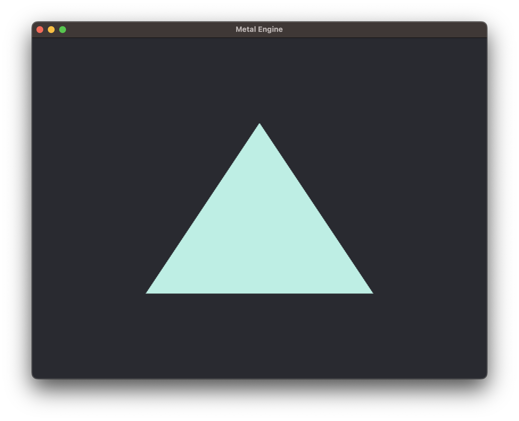
If you look closely at the edges of the triangle, you'll notice that it might look a bit fuzzy. The reason for this is due to a bug in GLFW. By default, our metalLayer resolution gets set to the resolution we specified in glfwCreateWindow(). Normally this wouldn't be an issue, but in MacOS the supposed window size doesn't necessarily correspond to the size of the image rendered within our window, aka our metalLayer or 'framebuffer'. This issue occurs due to DPI scaling within MacOS. On a high resolution monitor like a 4K monitor, or even on a Macbook Air Display, MacOS by default renders the UI at a "lower resolution" so that it appears larger on the screen. That's why if you ask GLFW what it's window size is, it will report 800x600, the values that we specified in glfwCreateWindow(), but if you ask what its framebuffer resolution is with glfwGetFramebufferSize(), it will likely be larger than that. It all depends on the scaling you have set in System Preferences. Anways, to counteract this issue, we'll need to make a few changes to our GLFWwindow and metalLayer creation:
void MTLEngine::initWindow() {
    glfwInit();
    glfwWindowHint(GLFW_CLIENT_API, GLFW_NO_API);
    glfwWindow = glfwCreateWindow(800, 600, "Metal Engine", NULL, NULL);

    if (!glfwWindow) {
        glfwTerminate();
        exit(EXIT_FAILURE);
    }

    int width, height;
    glfwGetFramebufferSize(glfwWindow, &width, &height);

    metalWindow = glfwGetCocoaWindow(glfwWindow);
    metalLayer = [CAMetalLayer layer];
    metalLayer.device = (__bridge id<MTLDevice>)metalDevice;
    metalLayer.pixelFormat = MTLPixelFormatBGRA8Unorm;
    metalLayer.drawableSize = CGSizeMake(width, height);
    metalWindow.contentView.layer = metalLayer;
    metalWindow.contentView.wantsLayer = YES;
}
metalLayer size should now be set to the internal frameBuffer resolution of the glfwWindow object, which will give us nice and sharp edges:
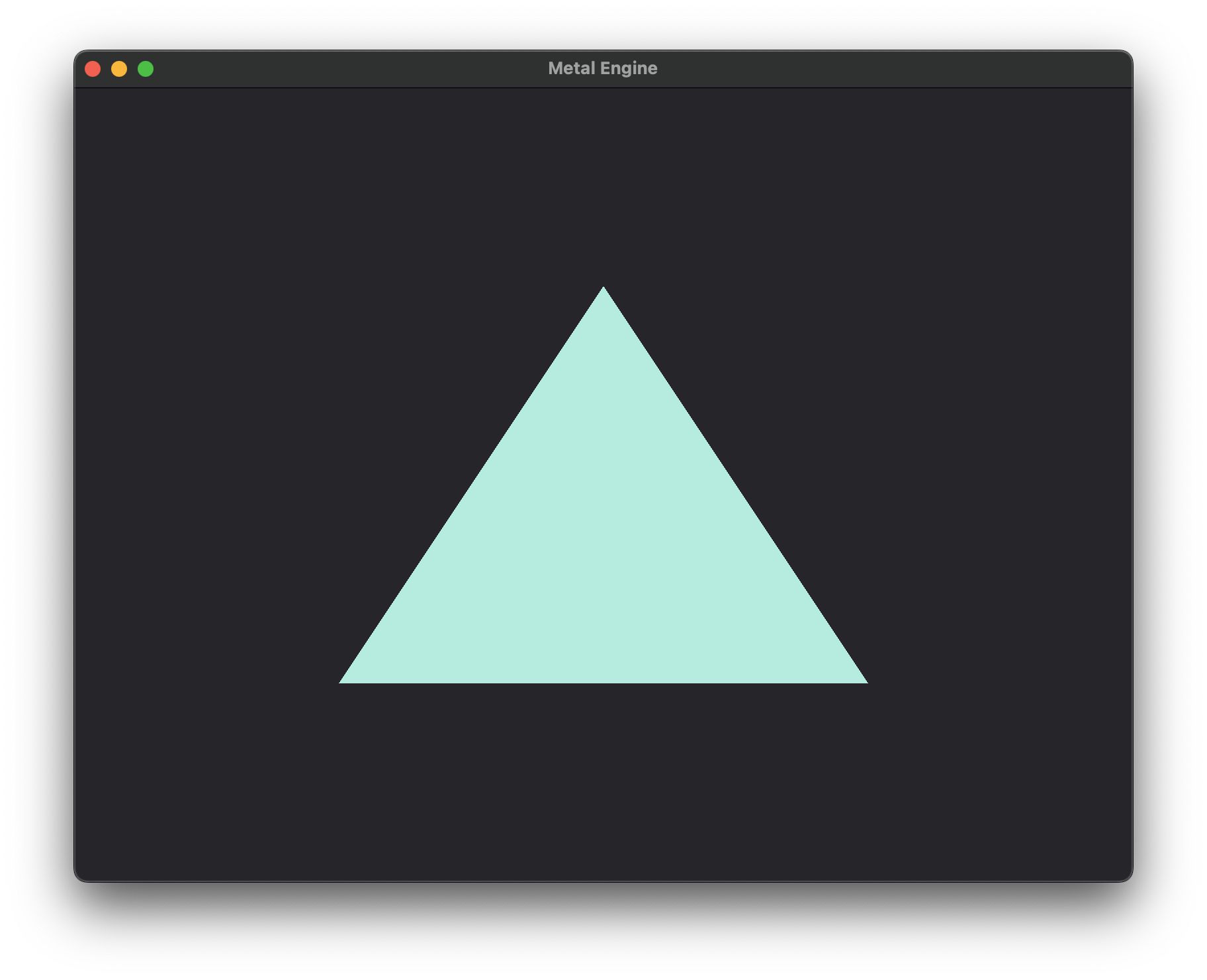
-
This image references the creation of Command Buffers, as described in the Apple Metal Docs article titled Setting Up a Command Structure. ↩